The page was added to provide tips and solutions for anyone building my projects. These tips relate not only to the specific manufacturers of components I use but may also be helpful for general use.
Let me say first, the brands I recommended here are in no way meant to be commercial endorsements beyond my own experience. I am not affiliated with any companies not am I being paid to endorse products. My recommendations come from my own experience with sourcing products for my own projects. I pay for all my components and if I endorse a product or company here it is for two reasons.
- I have found the products to be reasonably priced and of good quality, performance and reliability.
- Due to my familiarity with these specific brands I have resolved most issues that may occur and can provide resources here to help you overcome these same issues yourself.
You can source your components from anywhere you choose and many of you may already have most of the parts in your workshop.
ARDUINOS ARE NOT ARDUINOS
There is a wide range of manufacturers of Arduino modules. As a result there are compatibility issues that pop up from time to time. Most of these issues can be resolved fairly easily although they can be frustrating at the time. Usually a google search will provide a suitable answer to the most well known issues.
In my project I will usually recommend a specific brand of Arduino – not because it is better but because I have proven compatibility with it, and if issues arise I have already resolved how to fix them and can provide solutions here.
You are welcome to use any Arduino module you prefer or have handy. If you are already using them then you will probably already have resolved any compatibility issues (if any).
If you are new to the Arduino I recommend you use the same brand as I have to ensure minimal issues in getting your projects to work.
Here are some of the issues I have found and resolved.
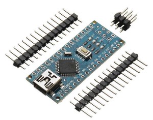
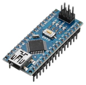
Geekcreit ATmega328P Nano-V3
The Geekcreit brand is the Arduino Nano I use. It is low in price, readily available and performs flawlessly. I buy mine from BangGood. The link is here:
If you buy from elsewhere make sure you order the ATmega328P version. There is also an ATmega168 version for a similar price but in only has half the memory and will not support the size of the Arduino software we are using.
Installing USB Drivers
The Geekcreit Arduino Nano uses a CH340 driver for USB communications. This is different from the original Nano and, if your PC has never connected to a CH340 device before, the Nano may not be recognised by your PC. If this is the case you will need to install the CH340 driver on your PC.
Here are the instructions:
Go to the manufacturers website here:
http://www.wch-ic.com/search?t=downloads&q=ch340
1) Click in the link labelled CH342SER.EXE.
2) On the next page click the DOWNLOAD button to save the file to your computer.
3) Run the file to install the drivers to your PC.
4) Now connect the Nano to your PC’s USB port. It should now be recognised by Windows. Note that if you are using a different operating system, there are USB drivers for a range of operating systems listed on the download page.
Installing Board Drivers
Before programming your Nano for the first time you will need to make several selections to allow the IDE to identify your board. For the Geekcreit Nano V3, follow these steps to install the required board drivers.
1) Connect the Nano to your PC’s USB port. If you have installed the CH340 USB drivers, your PC should connect without issue. If not, make sure you have installed the CH340 drivers first (described above).
2) Now to select the board. Select TOOLS from the IDE menu then select BOARD: A list of available boards will be listed.
4) Select BOARDS MANAGER from the top of the list. The Boards Manager window will open.
5) In the empty search bar at the top of the window, type Arduino AVR Boards and wait for the boards list to be populated. There may be more than 1 item listed but there should be only one called “Arduino AVR Boards”.
6) Hover the mouse over that item and see if the word INSTALL or INSTALLED appears. If INSTALLED is displayed, the board drivers are already installed and you do not need to do anything further. However, if INSTALL is displayed, click INSTALL to install the board software. When completed the word INSTALLED should be displayed.
Now close the Boards Manager window, then close the Arduino IDE (the new driver may not be recognised until the IDE is restarted).
1) Restart the Arduino IDE and select TOOLS from the menu. Scroll down to Boards and select “Arduino Duemilanove or Diecemila” from the list. The list will close and “Arduino Duemilanove or Diecemila” should be displayed alongside ‘Boards:’
2) Select Processor: from the TOOLS menu and select ATmega328P from the list.
3) Select PORT from the TOOLS menu and check that there is a USB option listed and that there is a tick next to it.
Your IDE should now be ready for programming your Geekcreit Nano.
For full details and training information on the use of the Arduino IDE please refer to the Arduino website at https://www.arduino.cc/
THE I2C BUS
Several of the components used in my projects connect to the Arduino via the I2C Bus. This is a serial connection designed for transferring data. One of its greatest advantages for these project is the small number of connections needed to connect these devices to the Arduino. For my projects I use I2C bus for some of my LCDs, clock modules and sensors.
Another advantage of the I2C bus is that it allows multiple devices to be connected to the Arduino at the same time with each device sharing the same connections. This means the Arduino needs some way to identify each device separately. To allow this, each I2C device has its own individual address in the same way that individual houses in a street have the own street number. Once we know the address values for each device we can specify them in the Arduino code allowing the code to select and talk to each device separately.
When buying I2C devices, the address is usually preset on the board. Sometimes there are jumpers or resistors on the board to allow you to select from one of two preset address. When you buy a specific brand of component, the manufacturer usually sets the same address across the entire production of that component. This means that if you are building multiple products that use that part, the address is predictable and its easy to replicate the product without needing to make changes to the software. However if you source the same part from a different manufacturer, you do not have the same predictability. The I2C address from one manufacturer may be quite different when sourced elsewhere.
This is another reason why I specify manufacturers for some parts. For parts that use an I2C bus, it means less work for the beginner who can assemble the project knowing the address already specified in the software will likely work. If you order the part from elsewhere you should be aware that the I2C address may be different. If so, this can be resolved, but it means there will be another complication in the assembly process to make the component work in your project.
By way of example, the default address for the 20 x 4 LCD I’ve used in the Morse Encoder and Decoder projects is 0x27. This value is specified as a hexadecimal number. If you open the Morse Decoder sketch into the Arduino IDE you will find the following line which sets the I2C address for the LCD display to 0x27 .
const int i2c_addr = 0x27; // Define LCD I2C bus addressIf your LCD uses a different address to this, it will not work with the original sketch so you will need some way to identify the LCD’s correct address and update the sketch to reflect the difference.
Enter the I2C Bus Scanner
The I2C Bus scanner is an Arduino sketch that will scan the I2C bus of your Arduino and report the addresses of any connected I2C devices it finds.
The link to the scanner is: https://github.com/djhumster/I2C_Scanner/blob/master/I2C_scanner.ino
Download this sketch and save it to your computer. Now open the sketch into your Arduino IDE and upload it to your Arduino. From the Arduino IDE menu, select TOOLS, SERIAL MONITOR. The Monitor window will open and display the results of the I2C scan. Identify the hexadecimal value of the device address as displayed on the monitor and write it down, as you will need to copy it into the Morse Decoder sketch shortly..
Once you have the address, reload the Morse Decoder sketch into your Arduino IDE and look for the following line somewhere near the top:
const int i2c_addr =0x27; // Define LCD I2C bus address
Replace the 0x27 with the address you wrote down from the scanner sketch the upload the Decoder sketch into your Arduino.
Note that this process applied to any I2C device you may have connected.

