Updated April 17: Released software version 2.0.1 which added the ability to easily change the labels on the preset-buffer buttons. This feature was added for users who prefer to store their own text in these buffers. You can now label the buttons to more readily identify your own buffer contents. The User Configuration section further below explains how to do this.
INTRODUCTION
This is version 2 of the VK2IDL Morse Code Sender, a significate update to the original version 1 which was released in 2020. Version 1 was based on an Arduino Nano coupled with a simple 20 x 4 LCD display. Version 2 was released in March 2025 has been completely redesigned using a relatively new development module called the ESP32-2432S028R, more commonly known in the maker world as the ‘Cheap Yellow Display’ or CYD.
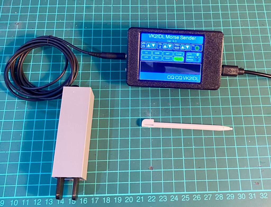
The VK2IDL Morse Code Sender functions as both a complete Ham radio morse sender and a portable Morse Practice device. It runs from any 5V USB power source so it can be taken anywhere. It is pocket sized yet contains most of the functions desired in a Morse Code sender.
- Morse code speeds from 5 to 35 WPM.
- Built-in speaker.
- Sinewave-quality side-tone generator with 4 levels of volume plus audio-Off.
- Adjustable side-tone frequency from 400Hz to 1000Hz in 100 Hz steps.
- Three lines of text to display your Morse as you send it. This includes one line of larger text to display your live morse
and two lines of smaller text displaying your Morse history. A ‘Clear’ button lets you clear the text between QSO’s. - Support for four keyer modes; Auto (for single paddles), Iambic A & B (for dual paddles) and Manual mode (for straight keys).
- Six preset buffers with common QSO phrases. The contents can be changed in the code if desired.
- Touch Screen controls for all functions and settings with no external buttons.
- Morse output is visually indicated by a simulated Green LED on the display.
- A single input socket for connecting your preferred key (Single paddle, Dual paddle or Straight key).
- An output socket to directly drive the ground-switched keyer input of your HF/VHF/UHF transceiver.
A number of user settings and options are pre-configurable by editing sections of the code (instructions included further below). This allows you to customise your own preset buffer contents as well as set your preferred defaults at start-up, including keying mode (i.e. Auto, Manual, Iambic A or Iambic B), Morse speed in wpm, side tone frequency and volume level.
A 3D Printed case is now available for this project.
NOTE: The downloadable files for this project (including for the 3D printed case) are at the bottom of this page.
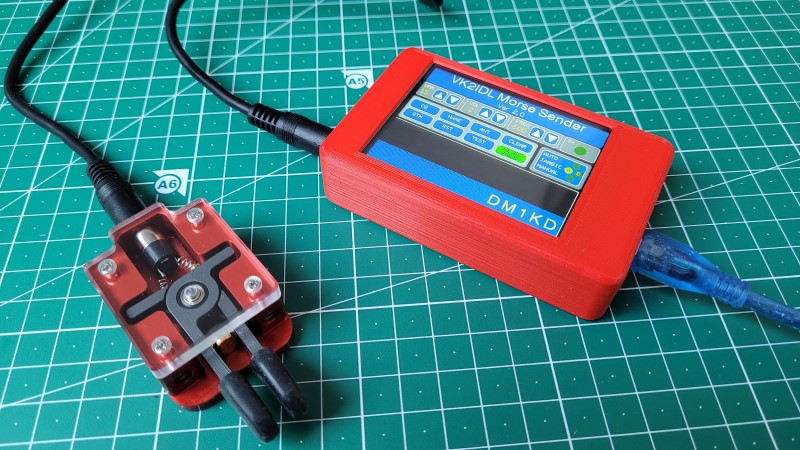
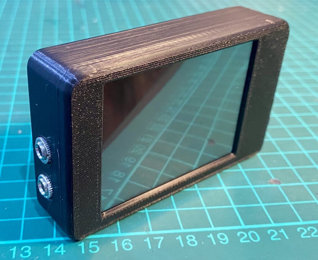
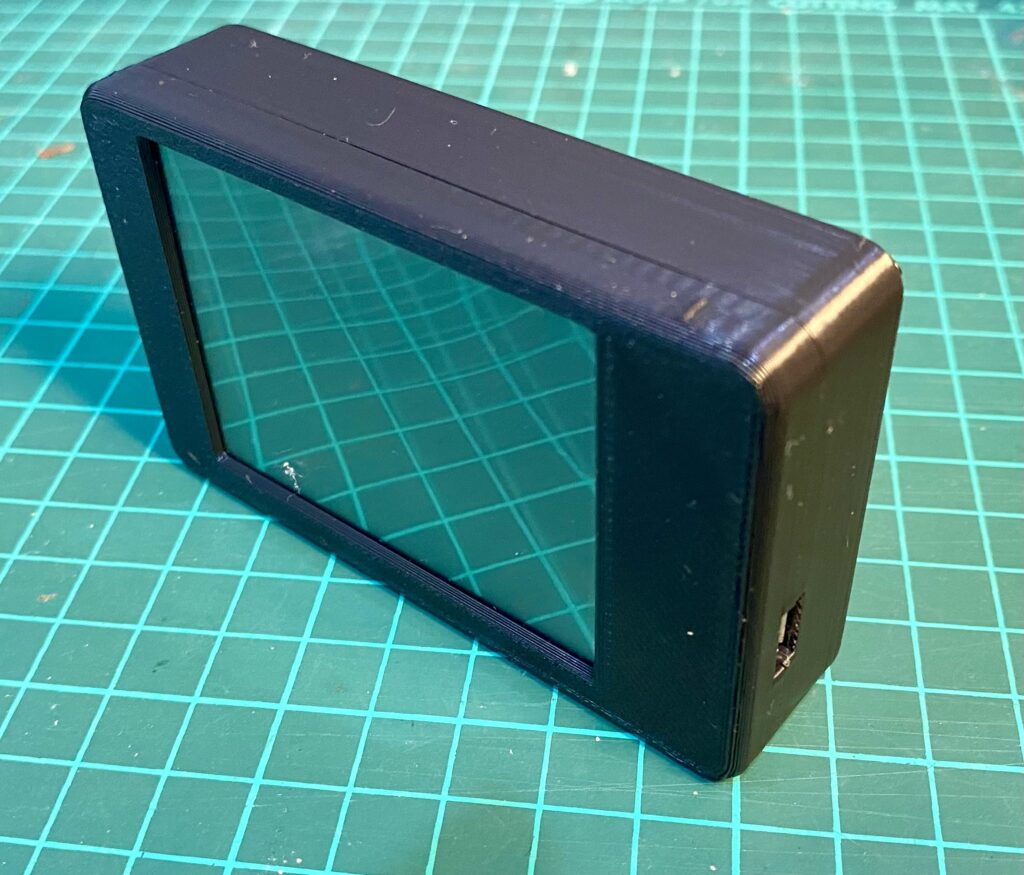
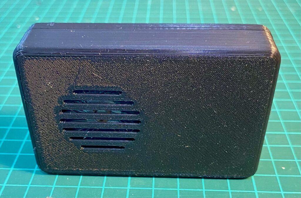
The photos below were sent to me by Klaus – DM1KD showing his assembled version of the VK2IDL Morse Sender in the 3D printed case.
What is the ‘Cheap Yellow Display’
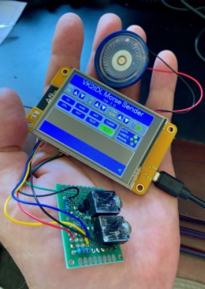
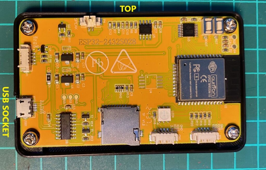
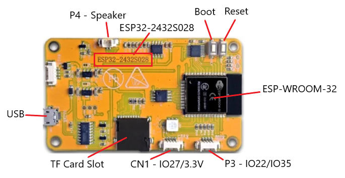
The ‘Cheap Yellow Display’ or CYD is a relatively new ESP-32 development board – part number ESP32-2432S028R. The board incorporates an ESP32-WROOM-32 module, a 2.8-inch 240 x 320-pixel TFT full colour LCD with resistive touch screen, a microSD card interface, an RGB LED, Digital to Analog Converter (DAC) with speaker output and a USB C or micro-USB port depending on the version. At the time of writing, the development module can be purchase for around AU$20 from AliExpress as well as from a number of other outlets.
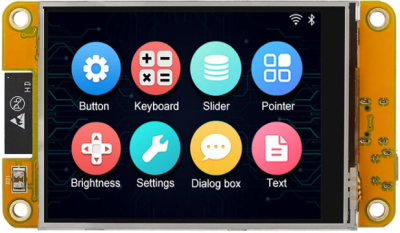
By using the CYD module, the Morse Encoder Sender 2 requires no switches, controls or LEDs. All controls and indicators are incorporated into the touchscreen display making the project extremely compact and very cheap to build.
An additional advantage is the size. When mounted in the 3D case (STL files included below) the new CYD Morse Sender module is truly pocket sized at just 90mm (W) x 55.8mm (H) x 23.5mm deep making it a device you can carry anywhere for Morse practice or field trips.
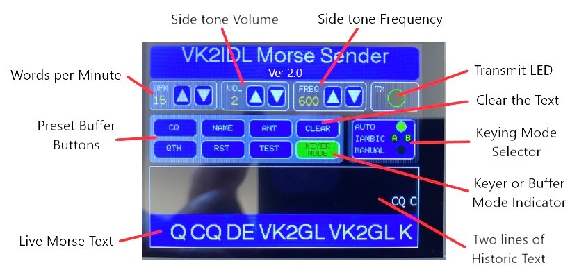
DISPLAY/FUNCTIONS
| Label | Description |
| Words per Minute | Displays the selected Morse speed in words per minute. Tap the Up or Down arrows to adjust the speed between 5 and 35 wpm. |
| Side tone Volume | Displays the selected side tone volume. Tap the Up or Down arrows to adjust the side tone volume from 0 (Off) through to 4 (Max) |
| Side tone Frequency | Displays the selected side tone frequency. Tap the Up or Down arrows to adjust the side tone frequency between 400Hz and 1000Hz. |
| Transmit LED | Lights GREEN as Morse is being transmitted through the output port to your radio. |
| Keying Mode Selector | Tap this button to cycle between keying modes: * If you have a single paddle key select AUTO. * If you have double paddle key select AUTO, Iambic A or Iambic B depending on your preference. * If you have a standard straight key select Manual. Note: A description of the differences between the IAMBIC A and B is included further below. |
| Clear the Text | Tap this button to clear the current Morse text from the display. You might wish to do this between QSO’s. |
| Keyer or Buffer Mode Indicator | Displays the operational mode of the unit. While sending Morse using the Morse key, this button is green and displays KEYER MODE. When you tap one of the preset buffer keys this button changes to yellow and displays BUFFER MODE. While Buffer Mode is active, press and hold the BUFFER MODE button to cancel the active buffer and return to KEYER MODE. Note: While in Keyer Mode, the KEYER MODE button has no function and simply indicates the selected mode. |
| Preset Buffer Buttons | Tap one of the six preset buffer buttons to send the contents of that buffer as Morse code. The green KEYER MODE button changes to yellow and displays BUFFER MODE. While in Buffer Mode all other keys and buttons (except the BUFFER MODE button) are disabled until the buffer has completed. |
| Historic Text Display | This area displays up to two lines of historic text which is automatically scrolled from the live text area below when that area is full. Text always scrolls in from the right-hand side in ticker tape format. |
| Live Morse Text | This area displays a single line of live Morse Code text as you send it. Text always scrolls in from the right-hand side in ticker tape format. Once this line becomes full, the older text will scroll from the left-hand end onto the historic text area above. |
OPERATION
Morse Speed Adjustment: Press the Up or Down buttons to increase or decrease the sending Morse speed in wpm. Minimum speed is 5wpm while maximum speed is 35wpm. The default setting is 15wpm (see User Configuration)
Volume Adjustment: Press the Up or Down buttons to increase or decrease the volume of the side tone. Minimum volume setting is 1 and maximum is 4. To switch the side tone off select 0. The default setting is 2.
Frequency Adjustment: Press the Up or Down buttons to increase or decrease the side tone frequency. Minimum is 400Hz and maximum is 1000Hz. The default setting is 600Hz.
Keying Mode Selector: Press the Keying Mode Selector button to cycle through the various keying modes. The default selection is Auto (see User Configuration).
- Single Paddle Key: Select Auto. This will automatically send Dits when the paddle is pushed to the right and Dahs when the paddle is pushed to the left. If you prefer this to be opposite simply change the wiring on your paddle to get the desired sequence.
- Double Paddle Key. Select Auto if you just want automatic Morse timing. For Iambic operation select your preference of Iambic A or B.
If you are not familiar with Iambic keying modes, Iambic keying sends alternating Dits and Dahs when both paddles are pressed at the same time. The difference between modes A and B is what happens when both paddles are released. In mode A, the keyer completes the element being sent then stops. In mode B, the keyer continues sending an additional element opposite to the one being sent when the paddles are released.
- Straight Key. If you have a standard straight key, select Manual. Your Morse code timing will be completely up to you with no timing assistance from the unit.
Clear Key: Press the CLEAR key to clear the Morse text display such as between QSOs.
Preset Buffer Keys: The preset buffer keys contain preset texts of commonly sent phrases. The buffer contents can be edited if required (see User Configuration). To activate a buffer simply tap one of the six buffer keys. The selected buffer will begin sending immediately and the green Keyer Mode indicator will change to a yellow Buffer Mode button to let you know you’re now in Buffer Mode. During this time all other keys (except the Buffer Mode key) are disabled and the WPM, VOL and FREQ buttons are greyed out. Once the buffer has completed sending, all functions will be re-enabled.
To cancel the Buffer Mode while it is still sending, press and hold the yellow Buffer Mode button. The buffer will then stop sending and the button will revert back to the green Keyer Mode indicator.
TX Indicator: The TX indicator simulates a Green LED and lights when Morse code is being send to the output port. The TX LED is of course synchronised with the side tone audio.
SCHEMATIC DIAGRAM
The ESP32 used in the CYD has a number of ports, most of which are already used to internally control the LCD and touch screen. In reality there are really only 4 available ports for connecting external devices and of these IO21 is shared. This leaves IO22, IO27 and IO35 free for our specific application. The CYD also provides an audio output to directly drive a small 8 Ohm speaker. Please refer to the schematic diagram below.
Note: The paddle wiring shown below connects the Left paddle to the Dah input and the Right paddle to the Dit input. Feel free to change these to suit your preferred paddle configuration.
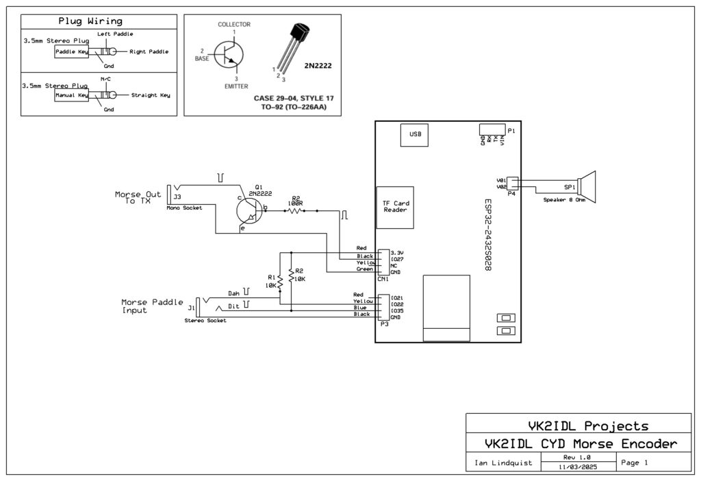
VK2IDL CYD Morse Encoder Ver 2.0 Schematic
TECHNICAL DESCRIPTION
Paddle keys are connected to IO22 and IO35 on the P3 connector. IO22 detects input from the Dah paddle and IO35 from the Dit paddle. The IO pins are biased positive using 10K resistors connected to the CYD’s 3.3V supply. This keeps them in a steady logic high state. Operating the paddle pulls each pin to ground which is detected by the software to generate Dits and Dahs.
Straight keys: Straight key are connected to IO35. When the Morse Sender is switched to Manual mode, IO22 is switch off and only IO35 is used to detect inputs from the Manual key and process them as manually generated Morse code. Avoid using a Mono plug for a straight key as the barrel of the plug will short IO22 to ground. While this won’t hurt the unit it will trigger a series of annoying Dahs whenever you switch out of Manual mode.
Morse Output: The Morse code output appears on IO27 on the CN1 connector. The pin is logic low by default but is pulled high by the software whenever Dits or Dahs are generated. IO27 is connected to the base of transistor Q1 causing it to switch on, pulling Q1’s collector low. The collector output acts as a grounding switch to operate the Morse Key input on your connected radio transmitter.
Speaker output: A small 8 Ohm 0.25w speaker is connected to the speaker socket P4. The Digital to Analog Converter (DAC) on the CYD board generates a nice sign wave signal producing a pleasant audio tone in the speaker. The volume and frequency are adjustable via the touch screen controls and the level is more than adequate for most applications. When not required it can be switched Off.
WIRING
PCB Connectors
The PCB connector colour coding shown on the schematic for CN1 and P3 may not match your connectors. The colours shown matched the cables I had available. I used the 4-pin connector supplied with the CYD board for P3 and the 4-pin connector from the vendor recommended in the parts list further below for the CN1 connector. If you used cables from these sources your colours may match the diagram otherwise you should probably follow the pin connections rather than the colour codes.
Morse Key Connections
Your Morse paddle or Manual Morse key should be plugged into the Morse input connector using a 3.5mm stereo plug. Your Morse key should be wired as shown in the appropriate diagram provided.
Paddle wiring
Connect your paddle key to IO22 and IO35 on the P3 connector. IO22 detects input from the Dah paddle and IO35 from the Dit paddle so wire your paddle accordingly to match your preferred Dit/Dah paddle configuration. The ground or common connection connects to the barrel of the plug.
Manual Key Wiring
Connect your Manual key to IO35 with the ground or common connection connected to the barrel of the plug. Although a Manual key only requires two wires, you should still use a stereo plug as a mono plug will short IO22 to ground pin to ground causing an annoying series of Dahs when cycling through the Auto or Iambic keyer modes. When Manual mode is selected on the Morse Encoder only IO35 is operational in the Encoder software.
Morse Operating Modes
- Select Auto mode when using single paddle keys. During Auto mode, only one IO pin input can be active at a time.
- Select Iambic A/B modes when using dual paddle keys. During this mode both pins can be active simultaneously allowing a sequence of alternating Dits and Dahs.
- Select Manual mode when using a straight key. All straight key inputs are detected on IO35 and inputs on IO22 are ignored.
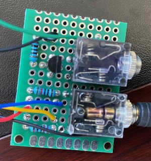
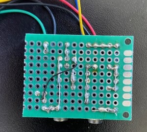
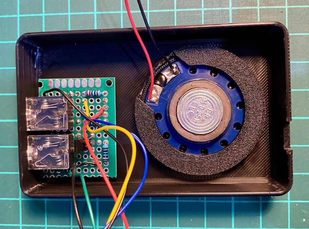
Interface Board
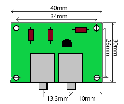
The interface board was built using some pro typing PCB. The circuit is quite simple, so I haven’t created a PCB for it. I have included photographs below of my protype. If using the included 3D case design, you should incorporate the board dimensions below. The two stereo sockets are mounted side by side directly onto the interface board so that the centers of the two shafts are 13.3 mm apart and the center of the right-hand socket is no more than 10mm from the right-hand end of the board. These dimensions will fit the mounting holes in the 3D printed case. If you choose to do your own installation method, then these dimensions are not critical.
LIBRARY INSTALLATIONS
The ‘Cheap Yellow Display’ requires the following additional libraries to be installed. The release version of the VK2IDL Morse Sender V2 uses the versions listed below and will work fine with these versions.
| Library | Description |
| DacESP32 by Thomas Jentzsch | Digital to Analog Conversion (DAC) library. This is used to create the audible side tone used to monitor your Morse code. This DAC library produces a pleasant sine wave tone into the connected speaker. Using version 2.0.0 |
| TFT_eSPI by Bodmer. | Graphics driver for the colour LCD. The ‘Cheap Yellow Display’ uses a 240 x 320 pixel ILI9341 TFT LCD Module. This driver specifically supports this module. Using version 2.5.43 |
| bb_spi_lcd by Larry Bank | Touch Screen Driver. While the TFT_eSPI driver does support the resistive touch screen on this LCD it has a number of issues that make it unreliable in this application. The bb_spi_lcd library provides an independent option that works perfectly and reliably. Using version 2.8.1 |
LIBRARY CONFIGURATION
If you have any issues with compiling your code using any of these libraries, please check which versions you have installed. The versions used for each library at the time this project was released are shown above. If you have installed a different version from a previous library installation and that library is not compiling, try downloading the specific version listed above which is known to work with this code.
Installing the TFT_eSPI Library:
The TFT_eSPI library supports the ILI9431 graphics chip used in the CYD’s colour display.
Open your Arduino IDE and go to Sketch > Include Library > Manage Libraries. The Library Manager should open. Search for TFT_eSPI. Select the TFT_eSPI library by Bodmer and install it.
Installing the DacESP32 Library:
The DacESP32 library is a Digital to Analog Conversion library. This is used in conjunction with the on-board DAC converter to create the audible side tone used to monitor your Morse code.
Open your Arduino IDE and go to Sketch > Include Library > Manage Libraries. The Library Manager should open. Search for DacESP32. Select the DacESP32 libraryby Thomas Jentzsch and install it.
Installing the bb_spi_lcd Library:
The bb_spi_lcd library supports the XPT2046 touch screen included with the LCD. There are other drivers available for this touch screen and even the TFT_eSPI library above supports it but I have found them unreliable. The bb_spi_lcd library works perfectly.
Open your Arduino IDE and go to Sketch > Include Library > Manage Libraries. The Library Manager should open. Search for bb_spi_lcd.Select the bb_spi_lcd library by Larry Bank and install it.
User_Setup.h Configuration File for TFT_eSPI Library
To properly use the TFT_eSPI library, you need a configuration file called User_Setup.h with the correct definitions. The TFT_eSPI library includes a default version of this file which you will need to manually edit to configure the driver to suit the rest of your hardware. To save this step, I have prepared an edited User_Setup.h file that is already configured for the CYD so you won’t have to make any configuration changes. You just need to download this file and move it to the correct folder. The preconfigured file User_Setup.h file is included with the download of the VK2IDL Morse Encoder V2 software file.
NOTE: There are numerous versions of the User_Setup.h file available on their internet. Do not use them as they are unlikely to match the required setup for this project. Use only the one included with this project’s software download.
Installing the User_Setup.h file
The User_Setup.h file must replace the original file of the same name installed by default with the TFT_eSPI library. To find where this file is, take the following steps (Note: These steps assume you are using the Arduino IDE).
1. In your Arduino IDE, go to File and open the Preferences menu.
2. Copy the Arduino IDE “Sketchbook location” path. In my case it is in C:\Users\Ian\OneDrive\Documents\Arduino
3. In your Windows PC File Explorer, enter or paste the sketchbook location path to open the Arduino folder (it’s usually under the Documents folder).
4. Open the libraries folder. You should see the TFT_eSPI library folder there. Open it.
5. You will see a list of files, one of which will be the default User_Setup.h file. If you want to save this original version of the file you can rename it to default_User_Setup.h or something similar. If not the original file will be replaced in the next step.
5. Copy the User_Setup.h file provided with this project, into the TFT_eSPI folder. If you have chosen not to rename the original file you can accept the option to overwrite it.
USER CONFIGURATION
There are a number of user configuration settings in the code that can be applied to customise the software for your use. There are also several default settings that you may prefer to adjust to suit your preferences. If you are not familiar with software editing or have no experience with Arduino code, it is highly recommended you ONLY make the changes recommended below.
User Settings
The following can be changed to suit your application or personal preference. Note that in the code, the comments associated with each user-adjustable setting is prefix with *** to help you identify that these values as User settings.
Minimum and Maximum Morse Speed Limits.
The encoder had not been tested the unit at speeds above 35wpm. There are no guarantees.
44     int wpm_Min = 5;              // *** Determines the slowest morse speed value
45     int wpm_Max = 35;             // *** Determines the fastest morse speed value
Default Side-tone Frequency.
Accepted values are from 400 to 1000 in 100 Hz increments. Values represent frequency in Hz.
47 int toneFreq = 600; // *** Set default morse tone frequency to 600 HzDefault Side-tone Volume
The Digital to Analog Convertor (DAC) uses 4 different scale values to set 4 preset volume levels. These values are 1, 2, 4 & 8. However, these values are inverse to what you might expect with the largest value of 8 representing minimum volume and the smallest value of 1 representing maximum volume. A corrected, more user-friendly value is displayed on the LCD with a minimum volume level of 1 and maximum volume level of 4.
To this end, there are three variables used to define the side-tone volume; ‘toneVol‘ which holds the actual DAC instruction that sets the volume level in the hardware, ‘toneVolCount‘ which is used to step the volume level up or down as you press the volume buttons and ‘toneVolPrint‘ which is the corrected value displayed on the LCD. See the table below. To set your preferred default volume level, choose the volume level you require from the lefthand column then set the three variables to the values shown in the adjacent columns. The code snippet shown immediately below the table shows the default values set in the supplied software with values for a medium volume setting.
Note that the volume can also be set to 0 which switches the audio off, however, this function is not done using variables and cannot be set as a default level.
| Volume | toneVolPrint | toneVolCount | toneVol |
|---|---|---|---|
| Low | 1 | 8 | DAC_CW_SCALE_8 |
| Medium | 2 | 4 | DAC_CW_SCALE_4 |
| High | 3 | 2 | DAC_CW_SCALE_2 |
| Maximum | 4 | 1 | DAC_CW_SCALE_1 |
54   #define toneVol DAC_CW_SCALE_4   // Set the default tone volume to DAC_CW_SCALE_4 (Medium Volume)
55   int toneVolCount = 4;            // *** Set the default tone counter value to 4 (Medium Volume)
56   int toneVolPrint = 2;            // *** Actual volume level to display on the LCD (level 2)
Default Keyer mode setting on Start-up.
Set just the desired mode to true and the other three to false. Default setting is autoKey
114    bool autoKey = true;          // *** Flag indicates whether Auto or Manual is selected
115    bool iambic_A = false;        // *** Flag indicates that Iambic A mode is selected
116    bool manualKey = false;       // *** Flag indicates that Manual mode is selected
117    bool manualKey = false;       // *** Flag indicates that Manual mode is selected
Default buffer contents.
The buffer contains preset messages that are often sent regularly during QSOs. Before using the Morse Code Sender you should change the following text in the buffers to match your callsign and equipment.
Change YR-CALLSIGN to your Callsign.
Change YR-NAME to your first Name.
Change YR-LOCATION to your Town, City or State.
Change YR-ANTENNA to a brief description of your Antenna.
147   char CQ_Mess[] = " CQ CQ CQ DE YR-CALLSIGN YR-CALLSIGN K ";            // *** CQ message - Insert your own CALLSIGN
148   char NAME_Mess[] = " NAME IS YR-NAME YR-NAME. ";                       // *** NAME message - Insert your own NAME
149   char QTH_Mess[] = " QTH IS YR-LOCATION. ";                             // *** QTH message - Insert your own LOCATION
150   char SIGNAL_Mess[]=" YR RST ";                                         // *** Readability, Strength, Tone message - * Nothing to change *
151   char ANT_Mess[] = " ANT IS YR-ANTENNA. ";                              // *** Antenna message - Insert your own ANTENNA DESCRIPTION
152 char CQTest_Mess[] = " CQTEST CQTEST CQTEST DE YR-CALLSIGN. "; // *** CQTEST message - Insert your own CALLSIGNNote: If desired you can change the entire text of each buffer to something more suitable for your application. Simply change the text between the ” “ but Do Not remove the ” “. Note that there is a space at the beginning and the end of each buffer message. This is done solely to format the text when displayed on the LCD. The space does not affect the Morse Code. It is recommended you include these spaces in your new message.
Set the default Morse Speed on start-up
Choose a default Morse Speed value between 5 to 35.
171 morseSpeed = 15; // *** Default Morse speed at switch on ** Change if different default speed is desired **Change the Text Displayed on the Preset Buffer Buttons
If you choose to change the text in any of the Preset Buffers (as described above) you can also change the name printed on the associated button to reflect your new message. There are six buttons arranged as shown immediately below. Each uses a variable to identify it (i.e. Butn_Label_1, Butn_Label_2, etc). Referring to the code snippet below, identify the button that matches the message you have changed then change the associated text value for that button (highlighted below in BOLD text). Do not remove the ” “ and Do Not exceed 6 characters otherwise the label won’t fit the button.
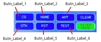
122   String Butn_Label_1 = "CQ";         // Define Label on Button 1
123   String Butn_Label_2 = "NAME";       // Define Label on Button 2
124   String Butn_Label_3 = "ANT";        // Define Label on Button 3
125   String Butn_Label_4 = "QTH";        // Define Label on Button 4
126   String Butn_Label_5 = "RST";        // Define Label on Button 5
127   String Butn_Label_6 = "TEST";       // Define Label on Button 6
INSTALLING THE SOFTWARE ON THE ESP32-2432S025 MODULE
Before uploading the software, you will need to install the ESP32 board support into your Arduino IDE.
Under the Tools menu go to the Boards Manager. Search for and install the following board support files:
- Search for “Arduino ESP32 Boards by Arduino” and install it. At the time of writing the current version was 2.0.18 – arduino.5
- Search for “ESP32 by Espressif Systems” and install it. At the time of writing the current version was 3.1.3
Once the ESP Board support is installed, go to the Tools menu and select Board, then select ESP32. Select the ESP32 Dev Module from the list.
Now plug your CYD into your PC and wait for it to connect. From the Tools menu select Port then select the displayed COM port. You should now be able to press the Upload button and upload the software to your board.
If you get compilation errors, you might want to check the following.
1. Check you have installed the required libraries. If any specific library is causing issues, check the versions in your Library manager. If they are different to those I used, try installing the same versions that I used (sometimes upgrades to libraries can cause incompatibilities with software based on earlier versions.
2. Check you have installed the User_Setup.h file included with this software otherwise your TFT_eSPI library won’t be correctly configured for the CYD board.
3. Check that you haven’t created syntax errors in the code due to configuration editing. If unsure, try installing the original INO file unedited and see if it will compile.
3D CASE INSTALLATION
The 3D printed case provides a complete housing for the Morse Sender project. Mine was printed on an Ender-3 V3 KE using Hyper PLA but you can use any suitable 3D print filament that’s compatible with your printer.
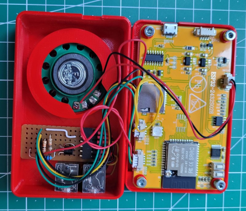
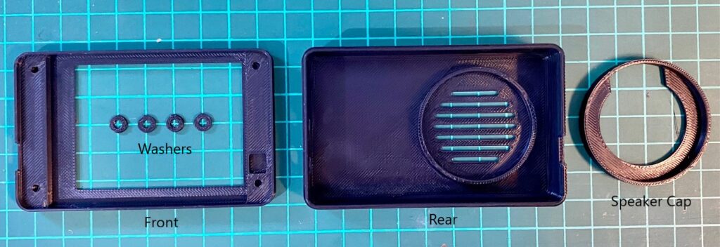
The case consists of 1 x case front, 1 x case rear, 1 x speaker cap and a set of 4 washers. In addition you will need four M3 x 6mm screws which are used to secure the CYD PCB to the inside of the front case. Once assembled, the two case halves clip together and do not require any further fasteners.
Note: When printing the 4 washers, apply a 10mm brim to the print setup as the washers are too small to stick to the print bed on their own.
The STL files for the 3D printed case are in the file download section at the end of this project page.
Assembly – Case Front
Install a washer onto each of the four M3 screws. The 6mm screws are a standard size and are a little longer than required so the washers are there to fill the gap. The washers are a firm fit so you will need to screw each M3 screw onto its washer until the washer is flat against the inside head of the screw.
Position the CYD board into the front case with the LCD towards the viewing window. The USB socket on the CYD must align with the small slot in one end of the case. Slide the top edge of the PCB (the edge with the speaker socket) towards the top edge of the case and align the 4 holes in the PCB with those in the case.
Install each of the screws and tighten lightly. The screws thread directly into the plastic and are easily stripped so do not over tighten them. They should be just firm enough that the washer lightly presses against the PCB surface and prevents any movement.
Case Rear:
The case is designed around having the two stereo sockets mounted directly onto the interface board. This allows the interface board assembly to be secured to the case using the nuts on the stereo sockets. The hole centers for the sockets are 13.3mm apart. Install the interface PCB by sliding the two sockets into the holes in the case. Apply the nuts and tighten.
Place the speaker into the speaker mount inside the rear case (with the magnet facing upwards). The speaker mount has an inside diameter of 39.5mm which matches the recommended speaker in the parts list. If using a different speaker please take this diameter into account when making your selection.
Orientate the speaker so the wires point towards the open space next to the interface PCB. The speaker cap is a friction fit. Simply press it firmly into place to secure the speaker.
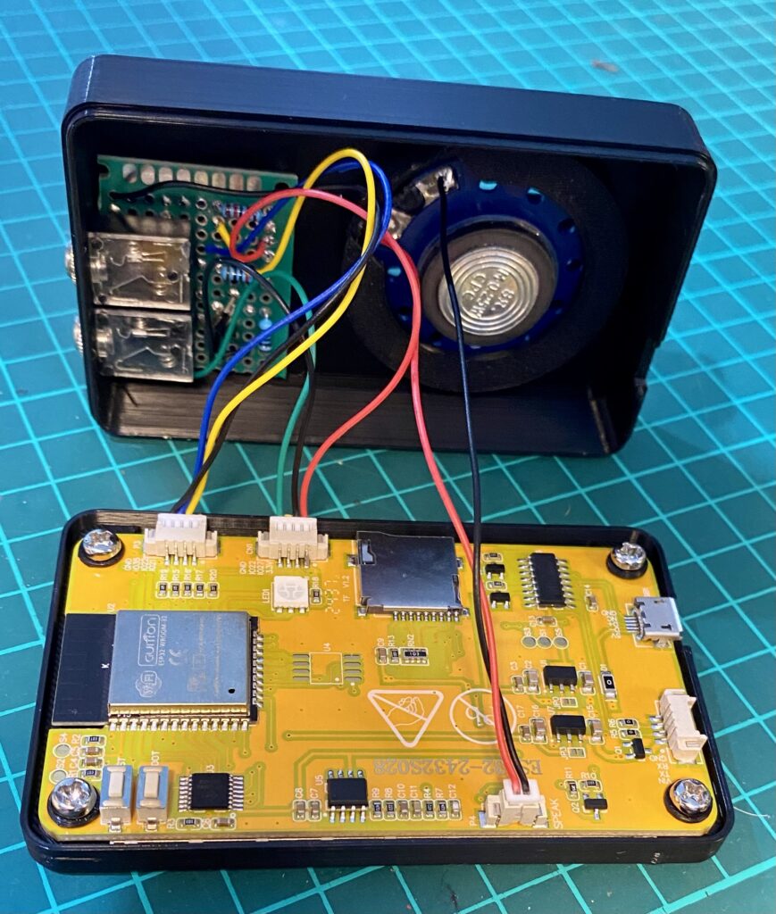
Final Assembly:
Plug the cables into the PCB. DO NOT mix the two 4 pin connectors. To prevent mix ups during assembly, I suggest marking one of the 4 pin plugs with black marker pen then do the same to the matching socket on the PCB.
Socket P3 connects to the Paddle circuit. Sockey CN1 connects to the TX output circuit and supplies 3.3V to the keyer circuit. Don’t forget to connect the speaker to the socket labelled SPEAK.
To fit the case halves, align the two halves along the side where the 4 pin connector are to ensure the wires are not pinched then press the two haves together. There are small grooves and slots along the long sides that lightly lock the two halves together. To open the case lightly pry open near the USB connector and the two halves will separate with light force.
Note: If you find the two case halves will not click together securely, try releasing the tension on the four screws holding the CYD display board. The front case walls are quite thin and easily distorted which can prevent the locking mechanism from correctly mating together.
HARDWARE/PARTS LIST
The following hardware is required to complete this project. As this project was developed in Australia some of the items were sourced locally. However, they are standard parts obtainable anywhere. I purchase many of my parts in bulk through AliExpress and keep them available for developing my projects.
Note: The ESP32-2432S028 CYD board is supplied with one 4-pin connector so you will need to purchase a second 4 pin and a 2-pin connector. For these see comments further below
| Item | QTY | Source |
| ESP32-2432S028 CYD board | 1 | AliExpress – ~AU$20 |
| **4-pin JS2 connector 1.25mm | 2 | AliExpress store “Sunny Business” – AU$3.11 |
| **2-pin JS2 connector 1.25mm | 1 | AliExpress store “Sunny Business” – AU$3.11 |
| 3.5mm Stereo Socket | 1 | Jaycar – Cat.No. PS0133 – AU$1.95 |
| 8 Ohm 0.25w 40mm mylar speaker | 1 | Jaycar – Cat.No. AS3004 – AU$9.45 |
| 10k Ohm resistors | 2 | Jaycar – Cat.No. RR0596 – AU$0.85 for pk of 10 |
| 100 Ohm resistor | 1 | Jaycar – Cat.No. RR0548 – AU$0.85 for pk of 8 |
| 2N2222 Transistor | 1 | Jaycar – Cat.No. ZT2298 – AU$0.40 |
| ** NOTES: 1. The 40mm mylar speaker listed above actually measures just under 39.5mm. The speaker mount in the 3D case is designed to be a friction fit for this specific speaker and any speaker that actually measures 40mm will not fit. Please take this into account if ordering an alternative speaker. The speaker specified is readily available from a number of sources around the world including AliExpress where they are listed as headphone speakers for under AU$5. 2. The ESP32-2432S028 CYD board is supplied with one 4-pin connector so you will need to purchase more to complete the project. When sourcing the 2-pin and 4-pin connectors for the CYD I had several deliveries of connectors where the plastic molding did not match the socket on the board. It took me several attempts to identify a source with the correct shaped molding. These were sourced through AliExpress from a shop called “Sunny Business”. They are available in packs of 10 complete, with 100mm wire tails and matching sockets (which you will not need). Each pack is just AU$3.11 plus shipping. They have both 2, 3, 4, 5 and 6-pin variants. You will need a pack of the 4-pin and a pack of the 2-pin. See AliExpress screen shot image below for these items from the “Sunny Business” trader. | ||
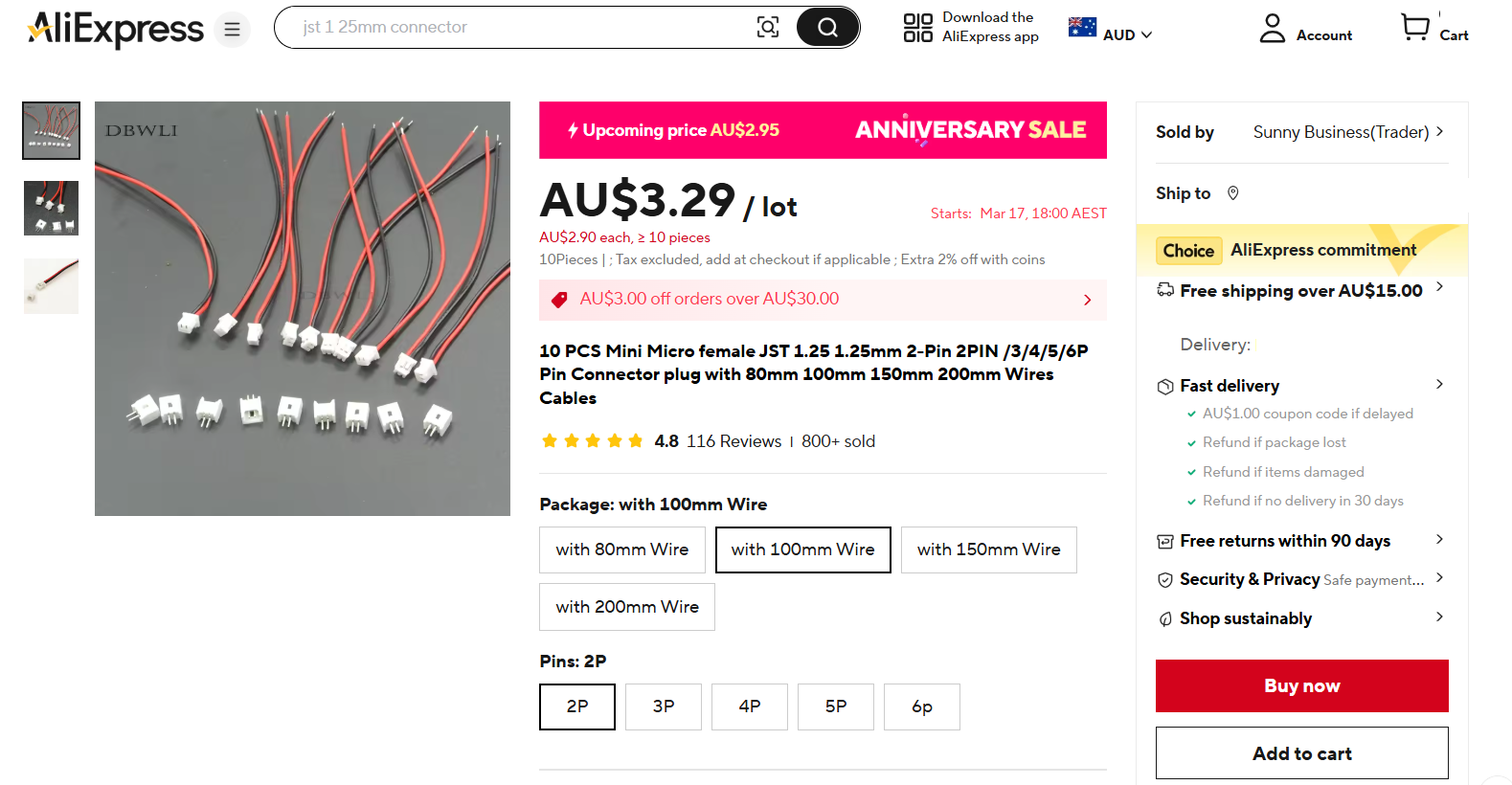
2-Pin and 4 Pin plugs to match the ESP32-2432S028 PCB
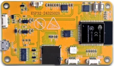
Sourcing the ESP32-2432S028 CYD board
The ESP32-2432S028 CYD board can be purchased from a number of different vendors on AliExpress. Be aware there are some non-genuine boards available as well as some physical variations so look for one that matches the image below. The original has a yellow board (hence its nickname) and has a layout exactly like the image below. The ESP32-2432S028 part number should be printed on it. The board may be supplied with either a USB C or USB Micro-B connector depending on the supplier. Each board is shipped in small plastic box and includes a USB cable, a touch screen pointer and one 4-pin connector cable. Most are available for AU$20 – $25 but can be available for a little less during sales promotions.
There are similar versions with a different layout. I have not tested them, nor have I checked their IO Port availability to see if they are compatible.
DOWNLOADS
VK2IDL V2.0.1 Morse Code Encoder software
- VK2IDL V2.0.1 Morse Code Encoder software in INO format (released 17 April 2025).
- User_Setup.h file required for configuring the TFT-eSPI library for this project.
- Schematic Diagram in PDF form
- STL files for 3D Printed Case.